

1. Concept of Air Compressor
An air compressor is the main component of an air supply system. It is a device that converts mechanical energy from a prime mover (usually an electric motor) into gas pressure energy, serving as a pneumatic generator for compressed air.
As a type of power machinery, a compressor reduces gas volume and increases pressure, generating a certain amount of kinetic energy that can be used as mechanical power or for other purposes.
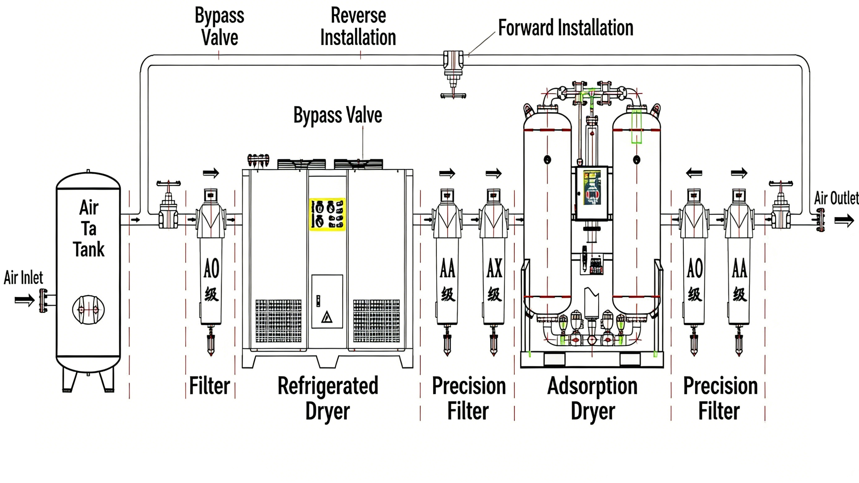
The schematic diagram of the compressed air system is shown below:
二, Classification of Air Compressors
1. Classification by Definition:
1)Volumetric air compressor: Reduces gas volume and increases gas pressure.
Converts mechanical energy into potential energy.
Reciprocating Compressor: The working volume changes periodically, while the spatial position remains unchanged.
Rotary Compressor: The working volume changes periodically, and the spatial position changes.
2)Dynamic Compressor
Increases the movement speed of gas molecules, converting the kinetic energy of gas molecules into gas pressure energy, thereby raising the pressure of the compressed gas.
Kinetic Energy → Potential Energy
Centrifugal compressor : it is a type of speed compressor. In this device, there is one or more rotating impellers (the blades are usually on the sides) that accelerate the gas. The main flow is radial.
2. Classification by Discharge Pressure
1)Blower: 0.01 ~ 0.1 MPa
2)Low Pressure: 0.2 ~ 1.0 MPa
3)Medium Pressure: 1 ~ 10 MPa
4)High Pressure: 10 ~ 100 MPa
5)Ultra-high Pressure: > 100 MPa
3. Classification by Displacement
Miniature: < 1 m³/min
Small: 1 ~ 10 m³/min
Medium: 10 ~ 100 m³/min
Large: > 100 m³/min
4. Classification by Cooling Method
1)Air-cooled: Uses air as the cooling medium, and completes air circulation with its own cooling fan.
2)Water-cooled: Uses water as the cooling medium, equipped with a dedicated cooling tower or a special cooling water circulation system.
5. Classification by Lubrication Method
1)Oil-lubricated
a. Oil-injected compressor
b. Micro-oil compressor
2)Oil-free lubricated
a. Water-lubricated
b. Dry screw
c. Oil-free piston
d. Centrifugal
3. Working Principle of Air Compressors
1. Piston Air Compressor
When the piston moves from the top dead center to the bottom dead center of the cylinder, the volume inside the cylinder increases and the pressure drops.
When the pressure inside the cylinder falls below the external atmospheric pressure, outside air pushes open the intake valve against the spring tension under the pressure difference and enters the cylinder (the exhaust valve remains closed).
When the piston reaches the bottom dead center, the cylinder is filled with air, and its pressure equals the outside atmospheric pressure.Due to the pressure balance, the valve spring closes the intake valve, completing the intake stroke.
As the piston moves upward from bottom dead center to top dead center, both intake and exhaust valves are closed, and the air inside the cylinder is compressed.
With the upward movement of the piston, the cylinder volume continuously decreases, and the pressure of the compressed air rises increasingly.This is the compression stroke.
When the pressure of the compressed gas exceeds the combined force of the valve spring tension and the pressure in the discharge pipe, the exhaust valve opens, and compressed air is discharged through the discharge pipe until the piston reaches the top dead center.
At this point, most compressed air in the cylinder is discharged, the pressure drops sharply, and the exhaust valve closes under spring tension.This is the discharge stroke.
The piston then moves downward again, drawing in fresh air and starting the next cycle.
The piston air compressor operates in repeated cycles of intake, compression, and discharge.
Note: Piston air compressors in the low-pressure market are now gradually being replaced by screw air compressors, so only basic understanding is required.
Screw air compressors are classified into two types:
twin‑screw air compressors and single‑screw air compressors.
1) Working Principle & Introduction of Twin‑Screw Air Compressor
A twin‑screw air compressor consists of a pair of parallel, intermeshing male and female rotors (or screws) rotating inside the cylinder.
This creates periodic volume changes in the spaces between the rotor grooves, so that air is continuously conveyed axially from the suction side to the discharge side.
In this way, the intake, compression, and discharge processes of the screw air compressor are completed.
The air inlet and outlet are located at opposite ends of the compressor.
The grooves of the female rotor and the teeth of the male rotor are driven to rotate by the main motor.
2) Working Principle & Introduction of Single‑Screw Air Compressor
A single‑screw air compressor is characterized by having only one screw rotor.
In practice, however, it has three rotating shafts: one screw rotor and two star wheels (planetary gears) perpendicular to the screw rotor.As a member of the screw air compressor family, the single‑screw air compressor offers advantages similar to those of the twin‑screw air compressor.However, it has not been widely adopted in industry due to several difficult technical problems that remain hard to solve.
a. Many moving parts:
The single‑screw air compressor has three rotating shafts.
Moreover, the rigidity of the screw rotor and the star wheels (planetary gears) differs greatly, leading to uneven deformation during operation.This makes it difficult to ensure accurate meshing, resulting in low volumetric efficiency.In commercially available single‑screw compressors, the star wheels are made of non‑metallic materials with poor wear resistance.During high‑speed operation, heavy wear increases internal leakage, causing a significant drop in flow rate after a period of use.Typically, after 3,000 to 4,000 operating hours, the flow rate decreases by an average of 5% to 10%.Therefore, the single‑screw air compressor has very poor economic efficiency in industrial applications.In addition, the uneven deformation and poor meshing accuracy reduce the mechanical stability of the whole unit, leading to high failure rates and high maintenance rates, which further limit its application scope.
b. The material of the star wheels (planetary gears) needs further improvement.
As one of the core components of a single‑screw compressor, the star wheels mainly function as seals.If steel star wheels are used, the large thermal expansion coefficient and expansion volume of steel require a relatively large clearance between the star wheels and the screw.This not only results in high leakage and low efficiency but also can easily cause seizure and major failures.If composite materials are adopted, the above problems can be avoided.However, current composite materials have low strength and poor wear resistance.Under shear force and mechanical friction during operation, they wear out quickly, leading to increased internal leakage and reduced efficiency.Frequent repairs also increase the workload of maintenance personnel and maintenance costs.Finding a material with high strength, low expansion, and high wear resistance has become another major problem for manufacturers.However, given the current progress in materials science, a fundamental solution is unlikely in the short term.
c. The screw profile needs further optimization.Due to the above two problems and the lack of effective solutions in the foreseeable future, the promotion of single‑screw air compressors is limited.Therefore, research institutions and major air compressor manufacturers have not invested much in the research of single‑screw profiles, and no significant progress has been made.Finding the optimal screw profile is another key task before large‑scale promotion.However, due to the poor market outlook, major manufacturers have not invested sufficiently, so fundamental improvement is difficult in the short term.
In summary, from the perspective of current technological development,twin‑screw air compressors are not only technologically advanced but also fully mature in practical applications.
3. Centrifugal Compressor
In a centrifugal compressor, the impeller with blades rotates on the compressor shaft.
Gas entering the impeller is driven to rotate by the blades, gaining an increase in kinetic energy (velocity) and static pressure head (pressure).The gas then leaves the impeller and enters the diffuser, where the velocity of the gas is converted into pressure, further raising the pressure.The compressed gas passes through the bend and return channel to enter the next-stage impeller for further compression until the required pressure is achieved.
4. Vortex type Air Compressor
A Vortex type air compressor consists of two scrolls with double-function equation profiles: an orbiting scroll and a fixed scroll, intermeshing with each other.During the intake, compression, and discharge process, the fixed scroll is mounted on the frame, while the orbiting scroll is driven by an eccentric shaft and restricted by an anti-rotation mechanism. It performs an orbital motion with a small radius around the center of the fixed scroll's base circle.Gas is drawn in through the air filter at the periphery of the fixed scroll. As the eccentric shaft rotates, the gas is gradually compressed in several crescent-shaped compression chambers formed by the meshing orbiting and fixed scrolls, and then continuously discharged through the axial hole in the center part of the fixed scroll.
5. Vane Air Compressor
A rotor is eccentrically installed in the compression chamber.There are 4 to 6 vanes on the rotor that can slide axially toward the rotor center.Springs are installed at the bottom of the vanes to keep the vanes in contact with the chamber at all times.